I have a hothouse whose nutrients are fed through the old Bluelab Pumps. Bluelab have been helpfully unhelpful in keeping this thing going except for where to buy pump parts - I've started doing quite a bit of hacking on it, and have come up with some hypothesis related to it. Below are my observations, hypothesis and notes. I don't guarantee anything on this page is right - indeed some stuff is likely incorrect. If you have questions, or more information, please feel free to reach out to me.
The actual pumps are Knight Pumps normally associated with dispensing washing liquid into commercial washing machines. Knight pumps can be reached at info@knightpumps.com.au. Pump kit is apparently KP5110DCS. W/T-66E is apparently appropriate. Part 000011. Flow rate is 300ml / minute at 24v DC 0.25 - 0.6 amp depending on load. This may also relate to pump KEI7010211 as per https://www.knightpumps.com.au/cmsAdmin/uploads/b_on_premise_global.pdf
The controller output is 24V DC.
I did successfully hack a replacement for the PH pump using a Honlite HPP=12-500-ZB-2-L 12 volt pump, with a stepdown of converter to convert 24v to 12v. Bought this all from Aliexpress. (I suspect they sell 24v pumps and they may be a better fit - I bought 12v for other reasons). I am extremely weary of attempting to replace the A&B nutrient pumps the same way as they may draw to much current for the transformer. (I have been unable to find the transformer specs).
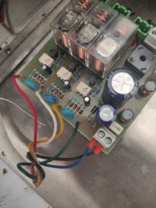
Recently the controller board blew up (I think it shorted when someone tried to replace a Knight pump without turning it off - it burnt a track on the board on the input - but surprisingly that appeared to be the extent of the damage) , so I spent some time working out the board. (I did fix it just by replacing the burnt track). After a bit of thinking, I suspect I have also deduced how this works - potentially providing enough insite that I can replace this with IOT equipment in the future. Here is what I measured on the circuit board, and my thoughts -
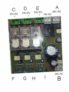
Per the picture below, I believe A and B are more-or less connected - save possibly for some filtering. My hypothesis - which is consistent with measurements I took is that B feeds back to the main sensor unit, which, when on, powers F, G and H with I being a common return. When B has its 25v power and the motors are running, F,G and H also read 25 volts AC (but 0 when the motor is not running, and 0 if B is not providing power.
C and D appear to be the A/B feed, E the PH feed. I expect these match with inputs F (red), G (White) H (Yellow) (The Blue and Black cables are providing power). I also note that each of F,G,H seems to have 4 diodes and some caps, leading me to believe that they are converting the AC to DC. This is then being fed to the white 6 pin IC 4N35 - which is an optocoupler, which appears to be driving some diods to switch relays. I have no idea what the 19v power is doing.
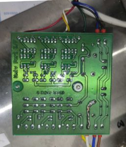
For anyone googling it, the writing on the back of the board is "G Baker Dec 03" and "Univ Peri I/F"
As an aside, The resistor to the left of "B" is 100k Ohms. I know this because it looked burnt so I pulled it out. I then realised it was actually fine and it was a trick of the lighting - I did replace it with another 100k resistor.